AD

Friday 1 September 2017

Soft UART - A UART software implementation for Raspberry Pi


1. Introduction


I am working on a personal project that requires two serial ports on a Raspberry Pi board. I used the embedded serial port plus a USB dongle for a while, but then I started wondering if there was a way of implementing a UART through one of the spare GPIO pins.

I searched the subject for a while and found many people wanting a software-based serial port on a Raspberry Pi. However, I could not find any ready-to-use solution - at least not in the way I wanted.

So I decided to create my own solution. For those who are not interested in the rest this article, here is the link:


2. Research


As I said, I searched for some ready-to-use solution. I found some examples of bit banging, but I wanted a kernel module able to emulate a TTY device. That would enable me to use this device with any application, such as minicom or gpsd.

I found the project RpiSoft-UART, which provides a character device able to transmit and receive data almost in the same way as a UART does. It still does not implement a TTY interface. For example, it does not allow changing the baud rate without reloading the module.

I also found the article Writing a Linux Kernel Module — Part 2: A Character Device. It is an excellent article describing how to implement a character device. It helps to understand the ideas behind the code written for RpiSoft-UART RpiSoft-UART.

Another interesting source of information was chapter TTY Drivers of the book Linux Device Drivers, 3rd Edition by Greg Kroah-Hartman, Alessandro Rubini, Jonathan Corbet. It explains how to implement a TTY device in details. It is outdated, as the TTY module structures have changed since the kernel 3.10. But it is still a good reading.

In the end, I found the project raspicomm-module. It is a kernel module for the RaspiComm extension board for Raspberry Pi. The hardware provides additional serial ports for a Raspberry Pi board, and the kernel module provides the software interfaces to the hardware as a TTY device. That helped to figure out the parts that were missing in the other references.


3. Implementation


In the end of the day, implementing a kernel module is a matter of filling the correct boilerplate - there are certain functions that the kernel expects to find in the module.

I tried to keep the implementation as simple as possible. There are three two important files:
  • module.c: Implements the interface between the module and the kernel (by filling the boilerplate).
  • raspberry_soft_uart.c: Implements the bit banging itself. A high-resolution timer is set according to the desired baud rate. Every time the timer goes off, a bit is written and/or  read to/from the GPIO pins.
  • raspberry_gpio.c: Implements the interface between the module and the GPIO, more or less as WiringPi.

4. Testing


The easiest way of testing it is connecting the selected Soft UART pins to the embedded UART pins. It would be like this:

GPIO 17 (pin 11) --- RXD0 (pin 8)
GPIO 27 (pin 13) --- TXD0 (pin 8)

There are more instructions on how to test it using minicom at 

5. Conclusion


My kernel module seems to work more or less as expected. I noticed that there are some communication errors in the reception, especially when the baud rate is faster than 4800 bps or when the CPU usage is high. The transmission works just fine.

I am not sure of what could be done to improve the reception, but I am open to suggestions.

6. References

Saturday 16 January 2016

Yocto on Raspberry Pi


I have been experimenting with Yocto on my Raspberry Pi for a while, and I thought it would be worth writing a brief introduction on how to do it...


1. Introduction


What is Yocto?

The Yocto Project is a set templates, scripts, tools, and methods that enable us to create custom Linux-based distributions for embedded systems regardless of the hardware architecture.

In other words, Yocto provides recipes to create your own Linux distribution to be executed on a specific hardware.

2. Motivation


  • It is a good value for your money. It is not as cheap as other boards, such as Arduino UNO, but it offers far more resources;
  • It is highly available;
  • It is quite popular among hobbyists and students.

Why Yocto?
  • It provides all the resources available in a Linux desktop: the same applications, libraries, and services. If the software we need to use on your platform is not provided by Yocto, then it is probably provided by OpenEmbedded;
  • It enables us to select the pieces of software included in the system. This way we can save resources by adding only what is needed, which is always an advantage when developing embedded systems;
  • It enables cross-compiling, which is faster and easier than developing your software on the target platform;
  • It is open-source (you can find the source code here).

3. Environment setup

  1. Create a working folder:$ mkdir ~/my_distro

    $ cd ~/my_distro


  2. Get the build system:
    git clone -b jethro git://git.yoctoproject.org/poky

    'jethro' is the nave of the current Yocto release.
  3. Get the BSP overlay for the hardware we are going to use, in this case Raspberry Pi:
    $ git clone -b jethro git://git.yoctoproject.org/meta-raspberrypi


  4. Set the environment variables required to build the image. You may specify the folder where the built artifacts will be stored. The folder will be created in case it does not exist. The minimal configuration files will be created as well.

    $ cd poky
    $ . oe-init-build-env ../build


  5. Add the Raspberry Pi overlay to the the file conf/bblayers.conf:

    $ vi conf/bblayers


    After editing the file, it will be like this:

    # LAYER_CONF_VERSION is increased each time build/conf/bblayers.conf
    # changes incompatibly
    LCONF_VERSION = "6"

    BBPATH = "${TOPDIR}"
    BBFILES ?= ""

    BBLAYERS ?= " \
      /home/adriano/my_distro/poky/meta \
      /home/adriano/my_distro/poky/meta-yocto \
      /home/adriano/my_distro/poky/meta-yocto-bsp \
      /home/adriano/my_distro/meta-raspberrypi \
      "
    BBLAYERS_NON_REMOVABLE ?= " \
      /home/adriano/my_distro/poky/meta \
      /home/adriano/my_distro/poky/meta-yocto \
      "

  6. Select the machine to target the build with:

    $ vi conf/local.conf

    ... and replace the line:

    MACHINE ?= "qemux86"

    ... with:

    MACHINE ?= "raspberrypi"

4. Building a very basic image

The most basic image available is rpi-hwup-image. To build it, type:

$ bitbake rpi-hwup-image


This will take a long time to complete in the first time you do it - remember it will download all the required source files and build the entire operating system from scratch! Once it is finished, the built image will be stored in: build/tmp/deploy/images/raspberrypi/rpi-hwup-image.rpi-sdimg


5. Writing the image to the SD card

It is very easy to write the image to the SD disk, but it is also very easy to do something wrong in the process. That is because we need to use dd as root. So be careful to not write the image into the wrong device (into the hard disk, for example). One thing I always do is verifying the connected devices using lsblk:

$ lsblk
NAME   MAJ:MIN RM   SIZE RO TYPE MOUNTPOINT
sda      8:0    0 931.5G  0 disk 
|-sda1   8:1    0   512M  0 part /boot/efi
|-sda2   8:2    0 923.1G  0 part /
`-sda3   8:3    0   7.9G  0 part [SWAP]
sdb      8:16   1   3.7G  0 disk 
|-sdb1   8:17   1    40M  0 part 
`-sdb2   8:18   1   3.6G  0 part 
sr0     11:0    1  1024M  0 rom  

This will show you the block devices connected to the computer. If you are not sure about which device is your SD card, then run lsblk, connect the SD card to the computer, and then run lsblk again. That will show the name of the device name of the connected SD card.

Once you have done that, type:

$ sudo dd if=tmp/deploy/images/raspberrypi/rpi-hwup-image.rpi-sdimg of=/dev/sdX bs=1M

... where /dev/sdX is the device name of the connected SD card.

This will create three partitions in the SD card:
This should be enough to boot the new operating system, but there is a detail to be solved: the created ext4 partition is exactly the same size as the built image - and it is full. So we need to resize it using a partition editor such as Gparted.

6. Conclusion

The procedure I described creates a minimal operating system for a Raspberry Pi. That operating system is based on an existing recipe and it is just enough to boot the hardware and provide a minimal command prompt.

I hope I have time to describe how to customize this minimal operating system and make it more useful though still saving resources.

Thursday 25 June 2015

FreeRTOS on Arduino UNO using Eclipse IDE: Part 3


Previous: Part 2.

In the last part of this tutorial, we are going to create a simple application.

7. Creating a FreeRTOS application


We are going to create a FreeRTOS version of the same "Blink" sketch we used to test the board and our development environment. Everything we are going to do now is quite similar to what we have done in the section 4 of this tutorial.


7.1. Create a new C++ Project and select AVR Cross Target Application / Empty Project as project type. Press next.


Creating a project.

7.2. Deselect the Debug configuration. Press next.

We don't need the Debug configuration.

7.3. Select ATmega328p as MCU Type. Press finish.


Selecting the MCU type.

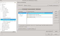
7.4. We need to add the folder /Source/include from the FreeRTOS static library project to the include directory path of our application project.
- Open the project properties and go to the section C/C++ General / Paths and Symbols.
- Click on Add...
- Fill the dialog according to the following pictures.

Adding FreeRTOS include folder to the include path.

Fill the dialog like this.

7.5. We also need to configure the linker so it find the symbols defined in the FreeRTOS library.
- Still in the project properties, go to the section C/C++ Build / Settings;
- Select AVR C++ Linker / Objects and add the object file as shown in the following pictures.

Adding FreeRTOS object file.

Fill the dialog like this.

7.6. Create a source file (e.g. main.cpp) and type (or copy) this code. The code has basically the same structure as the previous example.
- The main loop (responsible for blinking the LED) is in a separate function (not in main). This is used to create a task instead of being directly called;
- The function vTaskStartScheduler, called at the second line of the main function takes care of executing the tasks. The lines after that call are never executed;
- We need to create a callback named vApplicationStackOverflowHook, that will be executed in case of we run out of memory.


7.7. Build the project (press Ctrl+B). You will probably not find any problem.

7.8. Configure AVRDude. As we already created a programmer, everything we need to do is selecting it (we don't need to create it again).


7.9. Upload the software by pressing the "AVR" button on the toolbar. Sometimes Eclipse "forgets" the project on which you are working and complains that no AVR project is selected. If that happens, just select the project on Project Explorer panel and try it again.


Conclusion

After following this procedure, you will still have the same application you had at the beginning (using Arduino IDE). But you will have plenty of options to create multi-thread applications using threads, queues, semaphores, mutexes, etc. Your possibilities are limited only by your imagination (which I hope to be huge) and the available memory (which I know it is not that big).


FreeRTOS on Arduino UNO using Eclipse IDE: Part 2

Previous: Part 1

5. Create the FreeRTOS static library

We are going to create a static library containing all the FreeRTOS functions. After this is finished, we will link all the applications we create to this library. A lot of this process is about organizing the files provided in FreeRTOS package, and a little of it is really about codding.


5.1. Create a new C++ Project and select AVR Cross Target Static Library / Empty Project as project type. Press next.


Creating a project.

5.2 Deselect the Debug configuration. We don't need it as Arduino UNO board does not allow us to debug applications


We don't need Debug configuration.

5.3. Select ATmega328p as MCU Type. Press finish.

Selection the MCU type.

5.4. Download the file FreeRTOSV8.2.1.zip and extract it. After that, copy the folder Source into your project folder. As you can see in FreeRTOS documentation, the package contains various resources, such as example applications and guides, but all we need for now is the kernel source.


FreeRTOS package contents.


You will have a project like this:

FreeRTOS as an Eclipse project.

5.5. Remove all the portable layer folders in Source/portable, except for GCC and MemMag (I will explain the contents of these folders later). There are portable layers for many compilers, but we are going to keep only GCC.


Deleting unnecessary portable layers.

5.6. Remove also all the folders inside Source/portable/GCC, except for ATMega323. It is not the processor we are using (ATMega328p), but it is the most similar to it. So we are going to use as starting point.

ATMega323 portable layer.

5.7. Rename the folder ATMega323 to ATMega328p. It is not an essential step, but it will make your project more coherent.

ATMega 328p portable layer.

5.8. Remove all the files in Source/portable/MenMang, except for heap_2.c. As explained om FreeRTOS page, each of these files implement a different memory management model. We are going to stick with the model #2 because it enables the memory to be allocated and freed.


Memory management implementation file.

5.9. Open the project properties and go to the section Paths and Symbols. Click on Add...

Paths and Symbols section on project properties.

... and add Source/include to the include search path, as shown in picture below.

Adding include search path.

5.10. But there is still one missing header file. We will copy it from one of the example applications provided in FreeRTOS package. Copy the file FreeRTOSV8.2.1/FreeRTOS/Demo/AVR_ATMega323_IAR/FreeRTOSConfig.h to Source/include.

6. Adapt source files to ATmega328p

6.1. FreeRTOSConf.h

@line 73: Replace

#include <iom323.h>

for

#include <avr/io.h>

That is the generic header file for all AVR processors. It references other header files that are selected according to some processor being used (the right symbols must be defined for that to happen).


@line 90: Replace

#define configUSE_IDLE_HOOK 1

for

#define configUSE_IDLE_HOOK 0

This parameter enables us to define a callback function to be called when the system is in idle. In practice, it is a low priority task that is execute when there is no other task to be executed. It could be used to perform some background work or putting the processor in low power state. We don't want to use it now.

6.2. portable.h

@line 94: Replace

#include "portmacro.h"

for

#include "../portable/GCC/ATMega328p/portmacro.h"


6.3. port.c
This is probably the most important file as regards to porting FreeRTOS to a new processor.

@line 96: Replace

#define portCOMPARE_MATCH_A_INTERRUPT_ENABLE ((uint8_t) 0x10)

for

#define portCOMPARE_MATCH_A_INTERRUPT_ENABLE ((uint8_t) 0x02)


@lines 434 and 436: Replace TIMSK for TIMSK1.


@lines 447, 448, 460, and 461: Replace

SIG_OUTPUT_COMPARE1A

for

TIMER1_COMPA_vect


An that is it for the FreeRTOS static library. All we need to do not is creating some applications and link them to this library.


Next: Part 3

FreeRTOS on Arduino UNO using Eclipse IDE: Part 1


I have been playing with an Arduino UNO board during the last few days, and I wanted to see if it could do more than those "sketches". So I decided to try FreeRTOS on it. It turns out that I've got pretty good results!

I am going to show how to port FreeRTOS to an Arduino UNO board using Eclipse IDE. This tutorial is organized as follows:

Part 1:

  • Configure Eclipse as an Arduino UNO Integrated Development Environment (IDE);
  • Create, build and run a simple "Blink" application for an Arduino UNO board using Eclipse.
Part 2:
  • Create and build an Arduino UNO port of FreeRTOS as a static library;
  • Adapt source files to ATmega328p;
Part 3:
  • Create, build and run a FreeRTOS version of the "Blink" application.

By the way, all the source files are available here.


Arduino UNO clone I used in the tests.


Motivation

Why Arduino UNO
  • It is cheap;
  • It is open-source;
  • It is highly available;
  • It is easy to learn and use;
  • It does not require a separate piece of hardware in order to load new code;
  • It is popular among hobbyists and students.


Why FreeRTOS?

  • It enables us to implement multi-tasking (that is the main reason);
  • It supports both real-time tasks and co-routines;
  • It provides task notifications, queues, binary semaphores, and counting semaphores;
  • It also provides recursive semaphores and mutexes for communication and synchronization between tasks, or between real time tasks and interrupts;
  • It has a tiny footprint, which is good for boards with limited resources (such as Arduino UNO);
  • It has been designed to be small, simple and easy to use;
  • It is open-source (you can find the code here);
  • Royalty free.

Why Eclipse?
  • It is much richer in features than Arduino IDE;
  • It provides syntax-highlighting editor, incremental code compilation, a file/project manager, and interfaces to standard source control systems, such as SVN and Mercurial;
  • It has an extensive plugin library where you can find almost every feature you may need;
  • It enables us to work with many kinds of projects and programming languages so, if you already learned how to use it, you don't need to learn how to use another IDE.

Configuration

I am going to show how to make FreeRTOS work on an Arduino UNO board using Eclipse as IDE.

For this procedure I will use:
- Debian Jessie AMD64 as operating system;
- Eclipse Luna 4.4.2 64 bit as IDE;


1. Install the arduino package


The complete name of this package is AVR development board IDE and built-in libraries. You would not really need to install everything from this package, but it is the easiest way to get what we need: the built-in libraries. Just type:

$ sudo apt-get install arduino

This will install the Arduino IDE on you system. It is OK for simple projects, but it is quite limited in features and certainly does not fit our needs.


2. Test the board


Lets test the board and the installation of the Arduino libraries by running a simple test in the Arduino IDE.

2.1. Open Arduino IDE (it will be added to the laucher in the Development group). A dialog will probably be presented asking to add your user to the group dialout. That is necessary to access the board via serial line.

2.2. Open the “Blink” sketch example by accessing the menu File / Examples / 01.Basics / Blink.

2.3. Press the upload button (the second button on the tool bar). The software will be upload to the board and executed. You will see the onboard LED blinking. If it happens, everything is fine and you are ready to go on.

2.4. Things that may go wrong:

You may fail to access the board via serial line if you are not part of the dialout group. The Arduino IDE usualy verifies it and add your user to that group automatically. If that doesn't happen, you may need to add yourself to the group manually. In either case, you will need to logout and login again so the changes take effect.

You can verify the groups to which you belong by typing:

$ groups

You can add yourself to the dialout group by typing:

$ sudo usermod -a -G dialout username


3. Install and configure Eclipse IDE for C/C++ Developers


3.1. Download the Eclipse.

3.2. Extract it to the folder of your preference (let's say ~/deve/eclipse) and run it.

3.3. Install the AVR Eclipse Plugin. Access the menu Help / Marketplace, search for AVR, and click on “Install”. A next-next installation wizard will be presented. Just follow the presented instructions.


AVR Eclipse Plugin installation.


4. Test the Eclipse IDE


We are going the test out development environment by creating a simple application. This application will be an "Eclipse version" of the same "Blink" sketch we used to test the board before. You can follow the described steps or simply clone the project from my repository.

4.1. Create a new C++ Project and select AVR Cross Target Application / Empty Project as project type. Press next.


Creating a project.

4.2. Deselect the Debug configuration. We don't need it as Arduino UNO board does not allow us to debug applications (please let me know if I am wrong about that). Press next.

We don't need the Debug configuration.

4.3. Select ATmega328p as MCU Type. Press finish.


Selecting the MCU type.

4.4. Add the following source file to the project. You can type it yourself or get the file here.


Source file.


4.4. Build the project (press Ctrl+B). You will probably not find any problem.

4.5. Configure AVRDude. This step is necessary to tell the AVR Plugin how to access the board we are going to program.
- Open the project properties;
- Select AVR / AVRDude section;
- On "Programmer" tab, create a new programmer configuration by pressing the button "New";
- Programmer Hardware = Arduino
- Override default port = /dev/ttyACM0
- Don't you forget of selecting the created configuration on "Programmer" tab.


Creating a programmer configuration.

4.6. Upload the software by pressing the "AVR" button on the toolbar. Sometimes Eclipse "forgets" the project on which you are working and complains that no AVR project is selected. If that happens, just select the project on Project Explorer panel and try it again.


Well, now we have the tools we'll need to create our FreeRTOS static library and any FreeRTOS applications we want.

Next: Part 2.


Thursday 9 October 2014

Openning

Hello everybody!

This is the first post of my first blog.

I have been using information from blogs and discussion lists for a long time, but I have never contributed with any information. So I decided that it is time for me to start giving something back.

In this blog I will write some good things I have learned about:

  • Programming
  • Linux
  • Useful tools
  • Computing in general
I hope I have time to add good stuff here.

Cheers!